Extras din laborator
The Study of Voltage Resonance in RLC Series Circuits
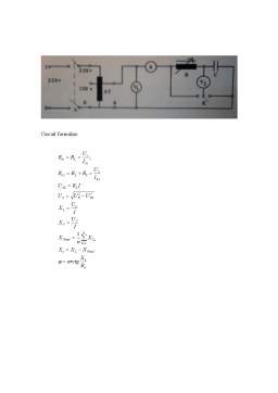
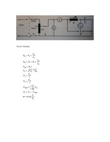
The scheme of the circuit used during the experiment is attached to the report.
Appliances list:
- AT - adjustable autotransformer, ATR 8 type;
- A - ferromagnetic ammeter, 2-10 A;
- V1,V2 - ferromagnetic voltmeters with multiple scales;
- R0 - 10 to max 20© rheostat;
- C - capacitor;
- I1 - bipolar switch;
- I2 - unipolar switch;
- K - unipolar switch.
Work purpose:
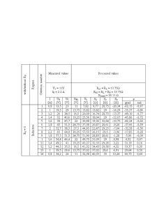
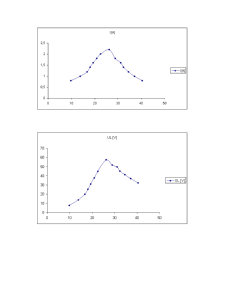
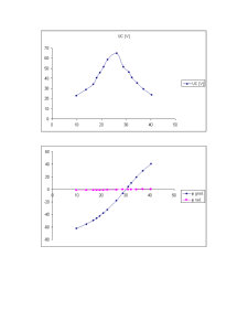
1) By alimenting the circuit with a voltage U, such that the maximum current would be I0 H 1.7A, the reactance of the coil modifies from the value (the core is completely introduced) to the minimum value, for the values of the current of 0.2, 0.4,…, 1.6; I0 = Imax; 1.6,…, 0.4, 0.2 by measuring the values of the voltage at the terminals of the coil and of the capacitor, in the following cases:
10) R0 short-circuited (R0 = 0, the voltage supply U1 H 10V)
20) R0 in the circuit (R0 ` 0, U2 H 30V or whatever necessary value such that I02 H I01)
2) For the measuring done at the point 1) it will be computed the amounts indicated in the table and it will be drawn the variation graphs I = I(XL), UL = UL(XL), Uc = Uc(XL), Æ = Æ(XL), for both cases 10 and 20 on the same graph.
3) It will be drawn at scale the phase diagrams of the voltages (it is recommended the scale 25V/1cm) for both cases 10 and 20 corresponding to a measurement in an inductive regime, at resonance, respectively to a measurement done in a capacitive regime.
Preview document
Conținut arhivă zip
- The Study of Voltage Resonance in RLC Series Circuits
- The Study of Voltage Resonance in RLC Series Circuits.doc
- untitled.bmp