Extras din proiect
Introduction
DC-DC converters are electronic devices that are used whenever we want to change DC electrical power efficiently from one voltage level to another.
Buck Converter - Theory of Operation
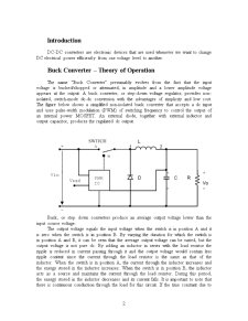
The name "Buck Converter" presumably evolves from the fact that the input voltage is bucked/chopped or attenuated, in amplitude and a lower amplitude voltage appears at the output. A buck converter, or step-down voltage regulator, provides non-isolated, switch-mode dc-dc conversion with the advantages of simplicity and low cost. The figure below shows a simplified non-isolated buck converter that accepts a dc input and uses pulse-width modulation (PWM) of switching frequency to control the output of an internal power MOSFET. An external diode, together with external inductor and output capacitor, produces the regulated dc output.
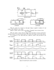
Buck, or step down converters produce an average output voltage lower than the input source voltage.
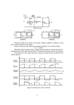
The output voltage equals the input voltage when the switch is in position A and it is zero when the switch is in position B. By varying the duration for which the switch is in position A and B, it can be seen that the average output voltage can be varied, but the output voltage is not pure dc. By adding an inductor in series with the load resistor the ripple is reduced in current passing through it and the output voltage would contain less ripple content since the current through the load resistor is the same as that of the inductor. When the switch is in position A, the current through the inductor increases and the energy stored in the inductor increases. When the switch is in position B, the inductor acts as a source and maintains the current through the load resistor. During this period, the energy stored in the inductor decreases and its current falls. It is important to note that there is continuous conduction through the load for this circuit. If the time constant due to the inductor and load resistor is relatively large compared with the period for which the switch is in position A or B, then the rise and fall of current through inductor is more or less linear.
The next step in the evolutionary development of the buck converter is to add a capacitor across the load resistor. A capacitor reduces the ripple content in voltage across it, whereas an inductor smoothes the current passing through it. The combined action of LC filter reduces the ripple in output to a very low level.
Any basic switched power supply consists of five standard components:
- pulse-width modulating controller
- transistor switch (active switch)
- inductor
- capacitor
- diode (passive switch)
The PWM(pulse-width modulating) controller
The PWM Controller compares a portion of the rectified dc output with a voltage reference (Vref) and varies the PWM duty cycle to maintain a constant dc output voltage. If the output voltage wants to increase, the PWM lowers its duty cycle to reduce the regulated output, keeping it at its proper voltage level. Conversely, if the output voltage tends to go down, the feedback causes the PWM duty cycle to increase and maintain the proper output. A buck converter or step-down switch mode power supply can also be called a switch mode regulator.
Transistors chosen for use in switching
Power supplies must have fast switching times and should be able to withstand the voltage spikes produced by the inductor. The input on the gate of the transistor is normally a Pulse Width Modulated (PWM) signal which will determine the ON and OFF time. Sizing of the power switch is determined by the load current and off-state voltage capability.
The power switch (transistor) can either be a MOSFET, IGBT, JFET or a BJT. Power MOSFETs are the key elements of high frequency power systems such as high-density power Supplies.
Preview document


Conținut arhivă zip
- Proiect Electronica de Putere - Buck Converter.doc
Alții au mai descărcat și

INTRODUCERE De la realizarea primului tranzistor bipolar (1947), s-a diversificat continuu gama dispozitivelor semiconductoare de putere (diode,...


3. Functionarea În general, pentru realizarea stabilizatoarelor de tensiune se folosesc proprietatile diodelor. Cel mai simplu tip de...
Te-ar putea interesa și

Tehnologia de fabricare a uleiului Uleiurile si grasimile vegetale comestibile prezente astazi pe piata de alimente reprezinta o chintesenta a...

1. SURSE REGENERABILE DE ENERGIE: NOTIUNI GENERALE 1.1. Introducere Omenirea a avut multe probleme de rezolvat pe parcursul istoriei sale de...