Cuprins
- Table of Contents
- 1. Introduction 3
- 1.1 Three-Phase Induction Machines 3
- 1.1.1 Structure and the principle of operation AC machines .4
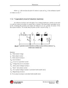
- 1.1.2 T-equivalent circuit of induction machines 5
- 1.1.3 Losses in induction machines .6
- 1.2 The presentation of eh-star-circuit method .6
- 2 Determination of stray load losses acc. to eh-star-circuit method 11
- 2.1 Algorithm for computation of stray load losses 11
- 2.2 The decomposition of measured phase currents in real and imaginary parts .15
- 2.2.1 Method A 15
- 2.2.2 Method B 16
- 2.2.3 Method C 17
- 2.3 MATLAB program .18
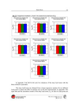
- 2.4 The comparison of methods A, B and C for measured motors .19
- 3 Mathematical model 26
- 3.1 Loss balance for induction machine in eh-star circuit 31
- 4 The influence of some parameters on the simulation of the stray load losses 35
- 4.1 The influence of temperature on simulated stray load losses .35
- 4.2 The influence of stator resistance on simulated stray load losses .38
- 4.3 The influence of iron losses on simulated stray load losses .39
- 4.4 The influence of friction and windage losses on simulated stray load losses .41
- 4.5 The influence of speed on simulated stray load losses .42
- 4.6 The influence of the phase lag Æeh on simulated stray load losses 43
- 4.7 The influence of the impedance ehZ on simulated current of positive and negative sequence system 45
- 4.8 The influence of Reh resistance on simulated stray load losses .46
- 4.9 The influence of the input power inelP, on simulated stray load losses 47
- 5 Influence of measurement parameters on eh-star results 48
- 6 Conclusion .50
- 7 Acknowledgement 51
- 8 Appendix 52
- 9 References 52
Extras din proiect
1. Introduction
The conventional losses and the stray load losses influence substantially the heating of the winding and reduce the efficiency of induction machines. The place and the size of the stray load losses must be determined in order to reduce them.
The determination of the stray load losses of an induction motor experimentally is not a simple task if it is to be performed with precision. There are of course International Standard (IEC 61972, IEEE 112…) test methods available. These standards need considerable time and expensive test equipment. A simple and cheaper alternative test is the eh-star-circuit test.
The eh-star-circuit is an asymmetric feeding of a three-phase induction machine (squirrel cage or wound rotor) like in the Steinmetz circuit. The unbalanced condition in the eh-star-test is obtained by operating the motor in star connection and then switching from normal 3 phase to single phase operation where the disconnected phase is connected back to the supply via a resistor of value similar to the motor’s locked rotor impedance per phase.
In this work an existing EXCEL-program for evaluation of stray load losses acc. to eh-star test will be modeled using MATLAB. The evaluation will be done with three different methods, which differ in the decomposition of real and imaginary parts of currents from measured values with correct phase angles. The influence of the measurement parameters on the evaluation of stray load losses with the three methods will be investigated and compared.
An existing mathematical model for asymmetric feed induction motor will be modeled using MATLAB. With this model the influence of same parameters e.g. eh-resistance, iron losses… on stray load losses will be simulated and investigated.
1.1 Three-Phase Induction Machines
Like other electrical machines, induction machines can be operated as either generators or motors. However, they are primarily used as induction motors.
Induction machines are by far the most common type of motor used in industrial, commercial or residential settings. (One notable exception may be in computer equipment, where there are significant numbers of motors used for hard drives, DVD players etc.) Depending on location (which affects other electrical energy uses, such as lighting, space heating) induction motors may consume up to 70% of all electrical energy generated.
1.1.1 Structure and the principle of operation AC machines
Of all the electrical machines, induction motors are the most common in industry due to their simplicity, rugged structure, cheapness and easy maintainability. There are two basic types of induction motors: single-phase induction motors and polyphase induction motors. Polyphase induction motors cover a variety of horsepower ratings and their use is preferred, if a polyphase power source is available.
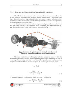
A three-phase induction motor is the most popular polyphase induction motor. It has two main parts: stator and a revolving rotor, which is separated from stator by a small air-gap. An exploded view of a cage induction motor is presented in Fig. 1.1.
Fig 1.1: Construction of a squirrel cage motor showing the stator (1), rotor (2),
end-caps (3), cooling fan (4), ball bearings (5) and terminal box (6) [4]
The stator construction of a three-phase induction machine is similar to that of a three-phase synchronous machine. A three-phase winding is placed in a number of slots in order to produce a rotating sinusoidal wave. Current flowing in the stator winding creates a magnetic field which rotates at synchronous speed, sÉ in radians per second, in rpm. sn
(1.1)
ssfÀÉ2=
ssppfnÉÀÅÅ==26060
(1.2)
f is supply frequency, is the number of pole pairs, slip is defined as:
Preview document


Conținut arhivă zip
- Determination of Stray Load Losses in Cage Induction Machines.pdf