
Extras din referat
Ergonomia Biroului de Marketing(EQUAL OBSERVATIONS)
For determining the position in space of the points on the topographic surface, it is necessary the measuring on site of the horizontal and vertical angles, and also of the distances between points. In land surveying , the measuring of the vertical and horizontal angles, and also of horizontal or inclined distances is done with the help of the theodolite or tacheometer.
The theme of the laboratory work
In order to make a topographic plan, which is to be used in studies concerning the town planning it is important to know how to use the tacheometer.
The application consist of:
a) Setting up the tacheometer over the station point;
b) Aiming the signal point;
c) Measuring of the horizontal angle between SA and SB aligniaments using the simple method(in both positions of the instrument);
d) Determination of the distance between the station point S and the aimed points A and B using both methods: the telescope in the horizontal plane and inclined plane.
Solving of the problem
Keeping and transporting the tacheometer is done in wooden or metal boxes, which protect them from shocks, dus and humidity. In the boxes there are also other accesories: the plumb bob, the compass, one screw driver a couple of keys etc.
On site, for the measuring with the tacheometer, the fallowing actions are executed:
a) Setting up the tachemoeter over the station point
For measuring, the tacheometer must be instaled in the correct position above the topographic point, marked on the soil by a post, sphere or bollard, named station point. This means that the principal axis of the tacheometer must coincide with the vertical of the station point.
Installing the tacheometer over the stating point requires several stages:
- The screws are weakened and the telescopic feet of the tripod are drawn taking it account the height of the operator and , after that , the position is fixed by assembeling the screws and fixing the feet in the ground. Then, the tacheometer is fixed on the small table of the tripod with the help of the tripod fixing screw, the plumb bob is attached and the tacheometer is brought above the topographic point.
- The centering of the tacheometer is done by moving the tripod's table in order to be approximately horizontal, after that, by fixing in the ground the tripod's feet. WIth these actions it is realised both the stability of the tripod and the bringing of the plumb bob over the topographic point. After these operations, the centering may not be perfect. In order to obtain a satisfactory centering , the tacheometer may be moved on the tripod's table until the plumb bob is projected on the mark on the soil. After the centering is considered perfect, the tripod fixing screw is assembled again.
- Fitting on the tacheometer is the operation of verticalisation of the principal axis, using the plane level tube and the three screws. The vernier plate is rotated, bringing the level tube in the position, parallel with the direction defined by two screws until the tube's bubble is brought between the two marks. Then the vernier plate is rotated about 100 degrees, bringing the level tube in the position, perpendicular on the first position, and, in this position, only screw number 3 is , bringing the bubble between the marks.
The Two operations are done two or three times until the bubble stays between the mark whatever position the tube is in the horizontal plan.
Fallowing these stages, the setting of the tacheometer in the correct position is realised. Thus the operator can begin the angular and linear measuring.
b) Aiming the signal points
Aiming is the operation of bringing the intersection of the cross hairs over the image of the topographic mark of the point. Before this the telescope must be fixed in order to obtain clarity of the cross hairs depending on the operator's eye.
The aiming of the topographic points is done in two stages. First, the telescope is aimed in the direction of the topographic point and, with the help of the collimator , the telescope is brought on the direction of the point. For this position, the movements in the horizontal and vertical plan of the tacheometer are blocked. Then, looking throught the ocular tube and acting the focusing screw or the muff it is realised the clarity of the image. After the aproximate aiming, using the collimator, the image of the point is brought in the telescop's field.
In the second stage, named the positions stage, the intersection of the cross hairs is brought over the signal point, using the screw for the fine movement of the telescope in the vertical plane and the screw for the fine movement of the vernier plate in the horizontal plan
Aiming of the signal points is done depending on the type of measured angles. Therefore when horizontal angles are measured, the intersection of the cross hairs is brought at the base of the rod, the vertical cross hair lapping on the middle of the signal. When the vertical angles are measured, the aiming is done with the horizontal cross hair at a height on the rod corresponding to that instrument's height at the station point, for measuring the slope angles, or at any height on the rod, on the church's tower, on the black box of the pyramid, in the case of vertical angles which are not slope angles.
Aiming of the topographic signal is done with a single position telescope or with both positions. In the first position of the telescope, the normal position, the vertical circle is found in the left side of the ocular, and in the second position, it is found on the right side. The second position obtained from the first position by rotating the telescope with 200 degrees in the vertical plane and iwht 200 degrees in the horizontal plane. In this way, the vertical circle passes from the left to the right of the ocular.
c) Measuring of the horizontal angle between AS and SB alignaments using the simple method(in both cases of the instrument)
The simple method consists in the measuring of the horizontal angles once, with one single position or with both position of the telescope. In this method, the difference between readings practice represents the general case of measuring, an angle being obtained from the difference between the readings done on the limb, with respect to both directions. When measuring the horizontal angles. also the vertical angles are measured.
Measuring the horizontal angle between directions SA and SB by the simple method is done in the fallowing stages:
- The tacheometer is fixed in the station point, S, it is centered, fit on, and the telescope is brought in the first position. Working with the recording movement, the horizontal circle remains fixed, and the first reading of the point A represents the angular value measured on the limb, from the zero division to the SA direction. The zero direction of the vertical circle is the direction of the zenith
The recording movement is realesed and the vernier plate is rotated clockwise, aiming the signal from point B. The reading on the horizontal and vertical circle is done, which are passed in, on the line coresponding to point B, in teh collumns 3 and 7. In this way, the measuring in the first position of the telescope is done. For checking the measurements and for obtaining a better precision, a second measurement is done with the telescope in the second position, bringing the vertical circle in the right side.
- The recording movement is released an the signal B is aimed. The reading on the horizontal and vertical circles is done and the values are written in the table, on the direction of the line corresponding to point B, in the columns 4 and 8.
- The recording movement is released and the vernier plate is roted counter clockwise, aiming back the signal A. The reading on the horizontal and vertical circles is done and the values are written in the table on the line coresponding to point A in the columns 4 and 8.
Measuring of the angular values of the horizontal and vertical directions in both positions is done.
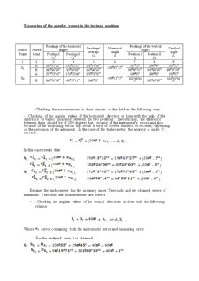
Measuring of the angular values in the inclined position.
Station Point Aimed Point Readings of the horizontal angles Readings’ average
Ci Horizontal angle
β Readings of the vertical angles Zenithal angle
Zi
Position I
CiI Position II
CiII Position I
Si Position II
Di
1 2 3 4 5 6 7 8 9
S1 A 392g13c22cc 192g13c27cc 392g13c26cc -106g87c23cc 101g55c 298g45c 101g55c
B 285g26c00cc 85g26c03cc 285g26c02cc 98g19c71cc 301g80c30cc 98g19c70cc
S2 A 372g73c43cc 172g73c45cc 372g73c50cc -104g15c55cc 100g97c 299g03c 100g97c
B 268g58c14cc 68g58c11cc 268g58c 101g36c61cc 298g65c40cc 101g35c60cc
Preview document


Conținut arhivă zip
- Measurements of Equal Observations.doc
Te-ar putea interesa și

Application nb.1 Surveying calculations The ensemble of operations in order to obtain plans and maps is known as surneying.Because during land...