Extras din laborator
1. Introduction
I. BPSK modulation/demodulation
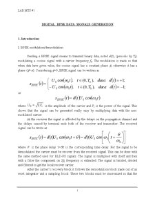
Sending a BPSK signal means to transmit binary data, noted d(t), (periodic by Tb) modulating a cosine signal with a carrier frequency f0. The modulation is made so that when data have given value, the cosine signal has a constant phase f; otherwise it has a phase (f+p). Considering f=0, BPSK signal can be written as
or
where is the amplitude of the carrier and Ps is the power of the signal. This shows that the signal can be generated really easy by multiplying data with the non-modulated carrier.
At the receiver the signal is affected by the delays on the propagation channel and the delays caused by terminal ends both of the receiver and transmitter. The received signal can be wrote as
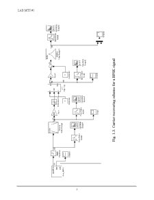
where q is the phase delay t=q/t is the corresponding time delay. For the signal to be demodulated the carrier must be recover from the received signal. This can be done with the same method used for BLD-PS signals. The signal is multiplied with itself and then with a filter the component on 2f0 frequency is extracted. The signal is limited, divided and filtered to get the local recover carrier.
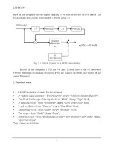
After the carrier’s recovery block it follows the demodulation block made out of an reset integrator and a sampling block. These two blocks must be sincronized so that the reset of the integrator and the signal sampling to be done at the end of a bit period. The block scheme for a BPSK demodulator is shown in fig. 1.1
Fig. 1.1. Block scheme for a BPSK demodulator
Instead of the integrator a FTJ can be used. It must have a cutt-off frequency between maximum modulating frequency from the signal’s spectrum and double of the carrier frequency.
2. Practical work
I. 1. A BPSK modulator is made. For this we need:
- A random signal generator – from “Sources” library- “Uniform Random Number”;
- One block for the sign of the signal – from “Math” library- “Sign” block;
- A sampling block – from “Nonlinear” library- “Zero Order Hold” block
- Local oscillator – from “Sources” library- “Sine Wave” block;
- Multiplying block – from “Math” library- “Product” block;
- The scope – from “Sinks” library “Scope”;
- Spectrum scope – from “Blockset&Toolboxes”/”DSP Blockset”/”DSP Sinks” library- “Spectrum Scope”.
They connect as it follows:
Preview document


Conținut arhivă zip
- Lab MUX_BPSK_1.doc
- Lab_MUX_QPSK_2.doc
- Lab_MuXTrSist3-last.doc
Alții au mai descărcat și


I.Studiul principalelor surse de zgomot. I.1. Se lanseaza programul unif_rand_demo.mdl. a)explicati rolul si functionarea fiecarui bloc din...


1. Presupun Vcc = +12V. 2. Punctul static de funcionare in regiunea activă este [Vce = 7,1 V , Ic = 4,8 mA] 3. Pentru acest exemplu se vor...


1. Fie structura de receptor cu filtru adaptat din figura: Unde ( ) ( ) ( ) g t s2 t − s1 t cu ( ) 1,2 s t =semnale binare egal probabile m(t)...

1)Sa se genereze un semnal s format din sumarea a 3 sinusoide armonice cu frecvente diferite. Formule folosite: A=1,2,3,…,1000 Semnalul...
Te-ar putea interesa și
I. Conditii impuse 1. Termometru digital cu 3 digiti care masoara 4 temperaturi 2. Gama de masura: -40˚ C÷100˚C 3. Eroarea de masura: ±0.5˚C (...

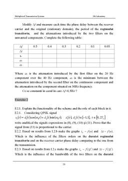
Chapter 1 MULTIPLE ACCESS TECHNIQUES 1.1. THE MAIN ACCESSING TECHNIQUES USED IN MOBILE COMMUNICATIONS: PERFORMANCE AND CHARACTERISTICS 1.1.1....