Extras din proiect
TEMA PROIECTULUI
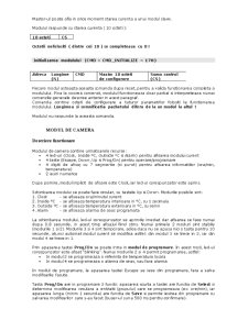
Transmite la modulul de camera temperatura interioara(canal 1,2,3,4),citita de la modulul de temperatura,doar la modificarea acesteia.
Transmite la modulul de camera Referinta de temperatura,la fiecare ora,din tabelul Referintelor de temperatura.
Ledurile rosii(L11,L14,L17) simbolizeaza comanda electrovalve ( on/off ) penru calorifere(modulul de intrari/iesiri).
Masterul va implementa un algoritm bipozitional de reglare a temperaturilor in camere Room i ( i=1,2,3 ) pe baza Referintelor de temperatura si a temperaturilor curente citite din camere.
Se ia in considerare si un histerezis in jurul referintei de temperatura.
Referinta pentru camera 1 poate fi setata local (de la modulul de camera) si transmisa la master.Ea este prioritara fata de referinta din tabel si este valabila pana la anularea ei tot de la modulul de camera.
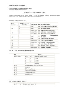
PROTOCOLUL UTILIZAT
Comunicatia se realizeaza pe portul serial.
Protocolul utilizat este H2(Home2).
DESCRIEREA PORTULUI SERIAL
Pentru comunicatie folosim portul serial – COM1 cu adresa 0x3F8h, adresa care este considerata Base Address pentru adresarea registrelor portului.
Registrele portului serial la PC :
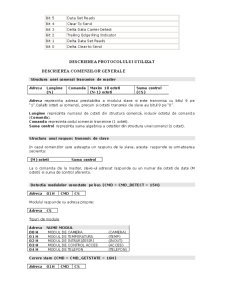
Base Address DLAB-Divisor Latch Access Bit Read/Write Abr. Register Name
+ 0 =0 Write THR Transmitter Holding Buffer
=0 Read RBR Receiver Buffer
=1 Read/Write DLL Divisor Latch Low Byte
+ 1 =0 Read/Write IER Interrupt Enable Register
=1 Read/Write DLM Divisor Latch High Byte
+ 2 - Read IIR Interrupt Identification Register
- Write FCR FIFO Control Register
+ 3 - Read/Write LCR Line Control Register
+ 4 - Read/Write MCR Modem Control Register
+ 5 - Read LSR Line Status Register
+ 6 - Read MSR Modem Status Register
+ 7 - Read/Write SR Scratch Register
First In / First Out Control Register (FCR)
Bit Notes
Bits 6 and 7 Bit 7 Bit 6 Interrupt Trigger Level
0 0 1 Byte
0 1 4 Bytes
1 0 8 Bytes
1 1 14 Bytes
Bit 5 Enable 64 Byte FIFO (16750 only)
Bit 4 Reserved
Bit 3 DMA Mode Select
Bit 2 Clear Transmit FIFO
Bit 1 Clear Receive FIFO
Bit 0 Enable FIFO's
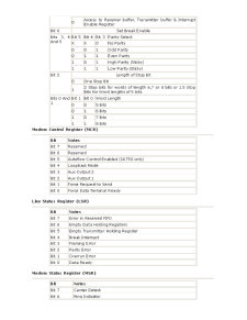
Line Control Register (LCR)
Bit 7 1 Divisor Latch Access Bit
0 Access to Receiver buffer, Transmitter buffer & Interrupt Enable Register
Bit 6 Set Break Enable
Bits 3, 4 And 5 Bit 5 Bit 4 Bit 3 Parity Select
X X 0 No Parity
0 0 1 Odd Parity
0 1 1 Even Parity
1 0 1 High Parity (Sticky)
1 1 1 Low Parity (Sticky)
Bit 2 Length of Stop Bit
0 One Stop Bit
1 2 Stop bits for words of length 6,7 or 8 bits or 1.5 Stop Bits for Word lengths of 5 bits.
Bits 0 And 1 Bit 1 Bit 0 Word Length
0 0 5 Bits
0 1 6 Bits
1 0 7 Bits
1 1 8 Bits
Modem Control Register (MCR)
Bit Notes
Bit 7 Reserved
Bit 6 Reserved
Bit 5 Autoflow Control Enabled (16750 only)
Bit 4 LoopBack Mode
Bit 3 Aux Output 2
Bit 2 Aux Output 1
Bit 1 Force Request to Send
Bit 0 Force Data Terminal Ready
Line Status Register (LSR)
Bit Notes
Bit 7 Error in Received FIFO
Bit 6 Empty Data Holding Registers
Bit 5 Empty Transmitter Holding Register
Bit 4 Break Interrupt
Bit 3 Framing Error
Bit 2 Parity Error
Bit 1 Overrun Error
Bit 0 Data Ready
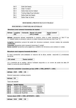
Modem Status Register (MSR)
Bit Notes
Bit 7 Carrier Detect
Bit 6 Ring Indicator
Bit 5 Data Set Ready
Bit 4 Clear To Send
Bit 3 Delta Data Carrier Detect
Bit 2 Trailing Edge Ring Indicator
Bit 1 Delta Data Set Ready
Bit 0 Delta Clear to Send
Preview document


Conținut arhivă zip
- Transmiterea la Modulul de Camera Referinta de Temperatura, la Fiecare ora, din Tabelul Referintelor de Temperatura.doc