Cuprins
- 1 CONTENTS 2
- 2 STATEMENT 3
- 2.1 Problem 1: Optimal Control of a DC Motor 3
- 2.2 Problem 2: Estimating the States of a DC Motor (Kalman Filter design) 3
- 3 PROBLEM 1 - SOLUTION. 5
- 3.1 State equations for the control system: 5
- The steady state feedback gain matrix: 6
- The optimal cost: 6
- The steady state solution of Riccati equation: 6
- 3.2 Conclusions 7
- 4 PROBLEM 2 - SOLUTION 8
- 4.1 Case a) 8
- Steady State Gain: 8
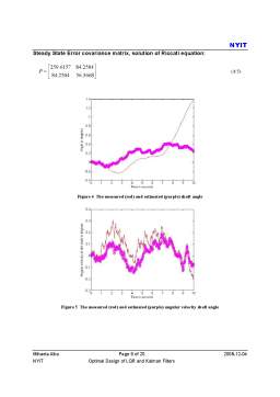
- Steady State Error covariance matrix, solution of Riccati equation: 9
- 4.2 Case b) i) 10
- Steady State Gain: 10
- Steady State Error covariance matrix, solution of Riccati equation: 10
- 4.3 Case b) ii) 11
- Steady State Gain: 11
- Steady State Error covariance matrix, solution of Riccati equation: 11
- 4.4 Conclusions 13
- 5 APPENDICES 14
- 5.1 Appendix 1: LQR Controller code from Matlab 14
- 5.2 Appendix 2: LQR Matlab results for DC motor shaft angle control 16
- 5.3 Appendix 3: Kalman filter implementation in Matlab for DC motor shaft angle estimation: 17
- 5.4 Appendix 4: Kalman filter results from Matlab for DC motor shaft angle estimation x1 and angular velocity x2: 19
- 6 REFERENCES 20
Extras din proiect
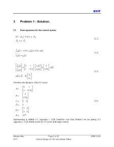
2 Statement
2.1 Problem 1: Optimal Control of a DC Motor
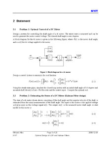
Design a system for controlling the shaft angle of a dc motor. The entire state is measured and can be used to generate the motor control voltage. The desired shaft angle is zero degrees. A block diagram for the dc motor is given in the following figure, where )(t is the motor shaft angle, and is )(tuthe dc voltage applied to the motor u(t)theta(t)1Product1sIntegrator11sIntegrator0.02Constant1 Figure 1: Block diagram for a dc motor Design a control system to minimize the cost function
Using the steady-state gains, simulate the closed-loop system with an initial shaft angle of 10 degrees and an initial shaft velocity of zero. Plot the state and the control input. Compute the optimal cost.
2.2 Problem 2: Estimating the States of a DC Motor (Kalman Filter design)
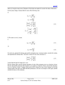
The state of a dc motor shown above, consisting of the shaft angle and the angular velocity of the shaft, is estimated from the noisy measurements of the shaft angle. The input to this motor is the applied voltage )(tuplus noise on this voltage signal)(tw. The output )(tm is the measured motor shaft angle. A state model for this motor is
with )(tv being the sensor noise. Estimates of both states are required to monitor the status of the motor. For this plant, design a Kalman filter for each of the following cases a)
For each case, generate the Kalman gain and the estimation error covariance matrix, simulate the system, and implement the Kalman filter. The initial condition for all of the simulations is:
Assume that the applied voltage u(t) is zero. Plot the Kalman gains and the standard deviations of each of the estimation errors as a function of time. Plot the state and the estimated state (together on one graph) as a function of time, and plot the estimation error as a function of time. Compare each result to those obtained in case a) and comment on how the changes made in the other cases affect the filter performance, the rate of convergence of the gains, and the standard deviations of the estimates.
Preview document


Conținut arhivă zip
- Optimal Control LQR and Kalman Filter.pdf
Alții au mai descărcat și


3. Functionarea În general, pentru realizarea stabilizatoarelor de tensiune se folosesc proprietatile diodelor. Cel mai simplu tip de...