Cuprins
- I. TECHNICAL NOTES
- II. CALCULUS FOR TEMPERATURE VARIATION
- II.1 THEORETICAL ELEMENTS
- II.2 DETERMINATION OF THE TEMPERATURE VARIATION
- II.3 CALCULUS FOR TEMPERATURE VARIATIONS
- III. STATICS AND STRENGTH
- III.1 SELF WEIGHT LOADS FROM CANTILEVERS
- III.1.1 CROWRING PLATE LOADS
- III.1.2 GRIDS SELF-WEIGHT LOADS
- III.1.3 REINFORCED CONCRETE WALLS SELF WEIGHT LOADS
- III.1.4 COATINGS SELF WEIGHT LOADS
- III.1.5 THERMAL INSULATION SELF WEIGHT LOADS
- III.1.6 SELF-WEIGHT LOADS FROM THE ASH FUNNEL STRENGTH STRUCTURE
- III.2 WIND LOADS
- III.3 SECTIONAL LOADS
- III.3.1 GENERALITIES AND COMPUTATION RELATIONS
- III.3.2 MEDIUM PRESSURES CALCULUS
- III.3.3 SHEAR FORCES CALCULUS
- III.3.4 SURFACES AND INERTIA MOMENTS OF THE SEGMENT MEDIUM SECTIONS
- III.3.5 WIND NOMINAL MOMENTS CALCULUS
- III.3.6 IIND ORDER MOMENTS DETERMINATION
- III.3.7 ELLIPSOIDAL MOMENTS CALCULUS
- III.3.8 AXIAL FORCES N DETERMINATION
- IV. REINFORCEMENTS DIMENSIONING
- IV.1 NOTATIONS AND CALCULUS SKETCH
- V. SECTIONAL CHECKINGS
- V.1 ULTIMATE LIMIT STATE FOR JOINTS OPENINGS
- V.1.1 NOTATIONS AND CALCULUS SKETCH
- V.1.2 THE UNITARY EFFORT DETERMINATION
- V.1.3 JOINTS OPENINGS CALCULUS HORIZONTAL SECTIONS CHECKINGS
- V.2 NOTATIONS AND CALCULUS SCHEME
- V.3 MAXIMUM UNITARY EFFORTS DETERMINATION IN STRESSED REINFORCEMENTS FROM VERTICAL AND HORIZONTAL LOADS
- V.4 MAXIMUM UNITARY EFFORT DETERMINATION AC IN EXTERIOR STRESSED REINFORCEMENTS
- V.4.1 THE CRACKS OPENINGS CALCULUS
- VI. SEISMIC CALCULUS
- VI.1 GENERALITIES
- VI.2 PROPER VIBRATION STAGE DETERMINATION FOR THE FIRST THREE MODES OF VIBRATIONS
- VI.3 IST STAGE OF THE FREE VIBRATIONS OF THE FUNNEL
- VI.4 IIND STAGE OF THE FREE VIBRATIONS OF THE FUNNEL
- VI.5 IIIRD STAGE OF THE FREE VIBRATIONS OF THE FUNNEL
- VII. FOUNDATION CALCULUS
- VII.1 GENERALITIES
- VII.2 PRESSURE DETERMINATION AT THE BASE OF FOUNDATION
- VII.3 EFFORTS DETERMINATION IN THE FOUNDATION
- VII.3.1 SYMMETRICALLY LOAD CASE A
- VII.4 EFFORT COMPOSITION FOR BOTH LOADING HYPOTHESIS
- VIII. STABILITY CALCULUS
- IX. MOUNTING TECHNOLOGY OF THE SLIDIING FORMWORK INSTALLATION
- IX.1 PREPARING WORKS FOR FOUNDATION WITHOUT BASE
- IX.2 SLIDING FORMWORK ASSEMBLING
- IX.3 SLIDING INSTALLATION ASSEMBLING
- IX.4 ELECTRIC POWER SUPPLY ASSEMBLING, COMMANDS AND LIGHTENING
- IX.5 TEGO FORMWORK OR STEEL PLATE FOR FILLING BETWEEN THE SLIDING FORMWORK AND FOUNDATION
- IX.6 CONCRETE PUMPING IN SLIDING FORMWORK AND THE MAKING-UP THE STRUCTURE THROUGH SLIDING, UNTIL THE ACCESS HOLE
- IX.7 THE SLIDING QUALITY
Extras din proiect
TECHNICAL NOTES
In this project it is presented the design and execution documentation of a funnel from a thermo-electrically factory. The funnel assures the burned gases release in the atmosphere (from the technological process of the factory), at a big height in order to assure gases dispersion in air, so that do not pollute the neighborhoods.
The burned gases have a temperature over the +200 C, so that the funnel is in category of “the hot funnels”. The soil geotechnical characteristics (on which is situated the funnel) are:
= 3.50 daN/cm² (for the fundamental load).
= 4.20 daN/cm² (for the exceptional load).
The elasticity modulus is assumed:
E = 150 daN/cm²
The free waters level is at 7.8 m over the base foundation. The funnel is made from concrete B 300 prepared with cement Pa 35. aggregates (gravel) with a maximum diameter 31 mm, reinforced with PC 52 and OB 37. through sliding from the foundation to top.
The funnel has a shape of a truncated cone, with an exterior diameter 14.90 m and the interior 14.00 m (at the base), and an exterior diameter 13.20 m and the interior 12.84 m (at the top).
The thickness of the funnel’s wall is changing with the height, decreasing from 40 cm at the base to 18 cm at the top.
The 307 ACI Comity standards permit for 6 m diameter, a wall thickness about 17.5 cm, increasing with 1.00 cm for each 1 m added to diameter.
In time of sliding process it will be executed the cantilevel from 10 to 10 m. On this cantilevel, it will be executed circular beams with reinforced concrete ribs. Those beams have a shape as a wheel with spokes, on which support brick masonry of the funnel.
The masonry, which assures the thermal and anti-corrosion protection, will be executed from antiacids ceramic plates putted with ARNOLEX-FN, (segments 10 m height).
The exterior thermo-protection of the masonry will be realized from spongy glass plates (dimensions 300 × 400 × 50 mm) with 2 3 mm joints filled with ARNOLEX-FN. Between spongy-glass masonry and concrete wall it was been provided an natural ventilation space.
At the superior part of the funnel will be executed an protection layer which must assure the anticorrosion protection, because at the contact gases, air, and water vapors will react and will form the acid drops (because of SO2 presence).
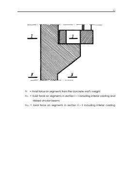
At the funnel base will be executed a space for ash collection denominated “ash pan”. The ash pan is situated under the ash funnel, which has at the middle a circular opening with 1 m diameter. The ash funnel is protected with antiacids masonry putted with ARNOLEX-FN. The bigger particles of ash, which cannot be disappear in atmosphere, fall down at the ash pan and are evacuated with special machinery.
The funnel foundation is designed on a general foundation plate made from reinforced concrete, with a circular shape, with 30 m diameter.
The wall reinforcement is composed from vertical and horizontal bars. The horizontal bars have a circular shape and will be mounted at the interior of the wall. The calculus was been made at the stability and ultimate limit strength. For the ultimate limit strength the calculus will be made in vertical and horizontal sections.
The horizontal sections (circular) are subjected to the compression axial forces, resulted from vertical loads action (over the section), as follows:
- the concrete wall own weight;
- the masonry and coating weight;
- the insulation weight;
- the circular beam weight;
- annex working weight;
and bending moments which acts in vertical plane, resulted from:
- eccentrically application of vertical loads;
- wind load;
- the temperature variation effect between interior and exterior side of the reinforced concrete wall.
The vertical sections are subjected to bending moments which acts in horizontal plane and are produced by:
- the temperature variation effect between interior and exterior side of the reinforced concrete wall;
- wind pressure ;
Preview document


Conținut arhivă zip
- Cuprins.doc
- Funnel (Industrial Chimney).doc